Anycubic Photon Workshop is a free slicer designed for Anycubic's resin 3D printers. Inside, you can find pre-configured settings tailored to the specific machine and resin, making slicing easier. This article is a detailed tutorial on how to add supports in Anycubic Photon Workshop V3.0.0 or higher, covering basic support settings, advanced support settings, and provides advice for creating support.
Related Articles Recommended List:
- Quick Start Guide for Anycubic Photon Workshop
- Description of Common Parameters
- Introduction of Key Parameters
- Introduction to 7 Tools
- Comparison of Support Tips
Basic Support Settings

(Model from Fabio Nishikata)
Generate Automatic Supports: The slicer will automatically create all the necessary supports, or you can choose to generate supports only for the build plate and the bottom of the model.
Manual Supports: You can directly click on the model to add support anchor points. These anchor points can be moved by dragging them with the mouse, and you can adjust their size or delete them in batches.
Support Angle: Increasing the support angle results in more supports being generated.
Anchor Distance: This parameter determines the distance between supports. A shorter distance leads to the generation of more supports.
Z Lift Height(mm): This setting is the distance between the model and the build plate. Raising the models before adding supports can prevent the model from fusing with the raft and protect the bottom of the model from damage during printing.
Advanced Support Settings
In the support setting window, you can configure the support script from light to heavy, and the Photon Workshop slicer also enables users to create custom support scripts. Follow the path: 'Support' - 'More Settings', and you will find many adjustable parameters related to settings for anchors, connections, bars, and the base.
Create and Custom A Support Script

Path: More Settings >> Add a Script >> Rename the Script >> Set the Support Parameters
Full Introduction of Support Parameters
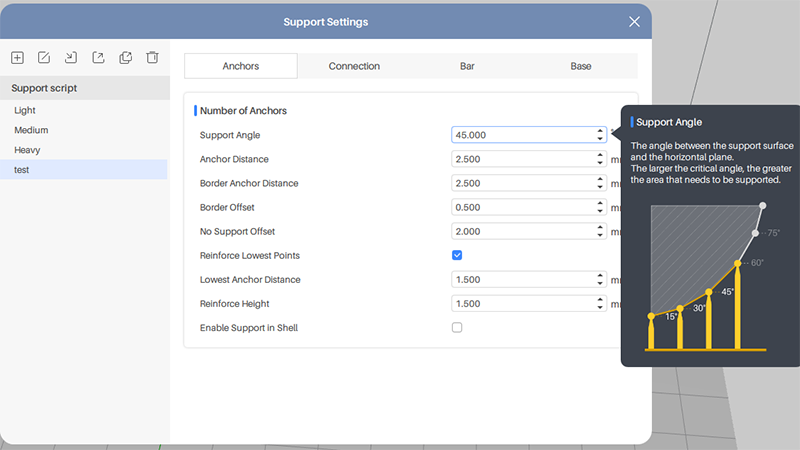
1. Anchor
Support Angle: The angle between the support surface and the horizontal plane. The larger the angle, the more supports are needed.
Anchor Distance: The distance between the internal anchor points. The shorter the distance, the more the supports.
Border Anchor Distance: The distance between the border anchor points.
Border Offset: The distance from the anchor to the edge of the model.
No Support Offset: The distance between the anchor points on the overhang. The shorter the distance, the more the anchor points.
Reinforce Lowest Points: Increase the anchor points at the lowest part of the models.
Lowest Anchor Distance: The distance between the anchor points at the lowest part of the models.
Reinforce Height: Increase the height of the supports on the lowest part of the models.
Enable Support in Shell: When active, the inner walls of the hollowed model will generate supports.
2. Connection
Distance in Model: The depth of the support tip inserted into the lower surface of the model. A greater length results in deeper support insertion, providing stronger support to the model; but this can also leave obvious marks when removing the supports.
Top Width: The width of the contact point inserted into the lower surface. The larger the width, the larger the contact area between the support and the model.
Length: The length of the top support that makes contact with the model's surface.
Tip Type: Set the tip perpendicular to the contact area or vertical to the horizontal plane.
Ball Contact: Set the contact shape as a ball.
Ball Diameter: The larger the diameter, the larger the contact area.
Break Point: Set break points where tips contact the models to make the support removal easier.

- Break Point Height: Length of the break point.
- Break Point Width: Width of the break point.
- Start Height: The distance from the top of the model to the break point.
- End Height: The distance from the break point to the tip inside the models.
Enable Platform Connection:
- Height: The height of the support platform.
- Radius: The larger the radius, the larger the support platform
- Slope Angle: The slope angle of the edge of the support platform.
3. Bar
Polygon Edge Number: The number of the support trunk.
Max Branch Number: The maximum number of the branches of the trunk.
Branch Top width: The width of where the branch contacts the model.
Branch Bottom Width: The width of where the branch contacts the trunk.
Trunk Top Width: The width of where the trunk contacts all branches.
Trunk Bottom Width: The width of where the trunk contacts the platform or the raft.
Trunk Height
- Automatic: Automatically generate the trunk height of the support.
- Max Height: Set the maximum trunk height to generate supports.
- Branch Max Angle: Set the maximum branch angle to generate supports.
Bar Cross Connection
Cross Type: MST Method - to ensure the anchor points are all being linked and the cross is less; Min2 Method - to ensure the anchor points are all being connected and the cross may be more; Border Method - only connect the anchors on the edge of the model.
Connection Type

- Start Height: The height of the end of the crossbar from the bottom of the support.
- Cross Bar Width: The width of the cross.
- Cross Bar Angle: The angle between the cross and horizontal plane.
- Interval Height: The distance between the cross.
4. Base
Add a base to increase the adhesion between the model and the print platform to reduce the risk of print failure like 3D print warping.
Plate Offset: The minimum distance between the support and edge of the base. The larger the offset, the larger the base.
Plate Height: The thickness of the base.
Slot Angle: The slope angle of the edge of the base.
Plate Type:

Perforation: Enable adding holes to the base to save resin.
- Hole Radius: The larger the holes, the less resinis needed, and the smaller the contact area with the print platform.
- Hole Interval: The larger the interval, the less the holes.
- Hole Edge Number: The larger the edge number, the more similar to the circle the hole is.
Adding Support Tips
1. Properly increase the support angle or decrease the anchor distance.
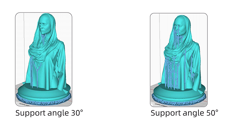
Increase support angle or decrease anchor distance, the support structure can be reinforced as additional supports will be created to some weak points.
2. Add manual supports after automatically generating supports.
Manually add support to some of the weak points to strengthen the support structure.
3. Check Islands
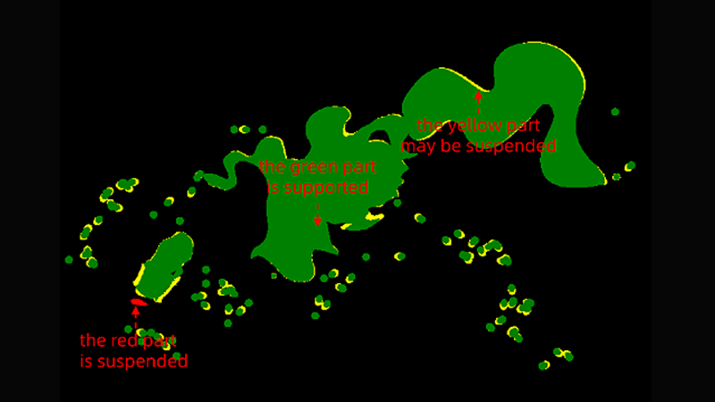
Click 'Check Islands' in the slice file preview interface, then drag the slider to inspect each layer. The green part indicates that there are sufficient supports and no additional support is required. The yellow part is the connected support but it may be hanging and might require additional support. The red part is entirely suspended and must have supports added, or it will cause 3D print support separation.